MRI Compatible Cable Design | RF Performance, 50Ω Impedance & MRI Safety Standards
MRI Compatible Cable Design for RF Performance & Medical Imaging Systems
MRI cable design is far more demanding than standard medical cable design.
A cable used in MRI systems must operate reliably under:
- Strong static magnetic fields (1.5T / 3T)
- High-frequency RF excitation
- Extremely sensitive signal acquisition conditions
This means an MRI cable must not only be non-magnetic, but also engineered for RF stability, signal integrity, and patient safety.
RF Behavior in MRI Systems
MRI imaging is based on nuclear magnetic resonance (NMR), where hydrogen (¹H) signals are excited and detected at a specific RF frequency.
Larmor Frequency
f=γB0
Where:
- f = resonance frequency
- ≈ 42.58 MHz/T (for hydrogen)
- = magnetic field strength
Typical MRI Operating Frequencies
| MRI System | Magnetic Field | Frequency |
|---|---|---|
| 1.5T MRI | 1.5 Tesla | ~64 MHz |
| 3T MRI | 3.0 Tesla | ~128 MHz |
At these frequencies, cables behave as RF transmission lines, not just electrical wires.
Poor cable design may cause
- Signal reflection
- RF noise coupling
- Signal attenuation
- Image artifacts
50Ω Impedance Control (RF Transmission Performance)
MRI RF systems typically require:Characteristic impedance: 50Ω ± 2Ω( some may 50Ω ± 5Ω)
Why Impedance Matters
Proper impedance control helps:
- Reduce signal reflection (low return loss)
- Maintain stable RF transmission
- Improve signal-to-noise ratio (SNR)
- Ensure reliable imaging performance
Engineering Design Approach
To maintain stable 50Ω impedance:
- Conductor size must be precisely controlled
- Dielectric materials must be RF-stable (FEP / PTFE)
- Cable geometry must remain consistent during bending
Capacitance & High-Frequency Stability
In MRI cable engineering, capacitance is not usually specified directly by customers, but it strongly affects RF performance, especially at higher frequencies.
Engineering Considerations
Lower capacitance helps:
- Reduce RF signal attenuation
- Improve stability at higher frequencies (e.g., 3T MRI ~128 MHz)
- Maintain signal integrity over longer cable lengths
Practical Impact
For long cable assemblies or multi-coax structures:
- Excess capacitance may lead to signal loss
- May affect tuning and matching performance
In professional MRI cable design, capacitance is optimized together with impedance and shielding — rather than treated as a single isolated parameter.
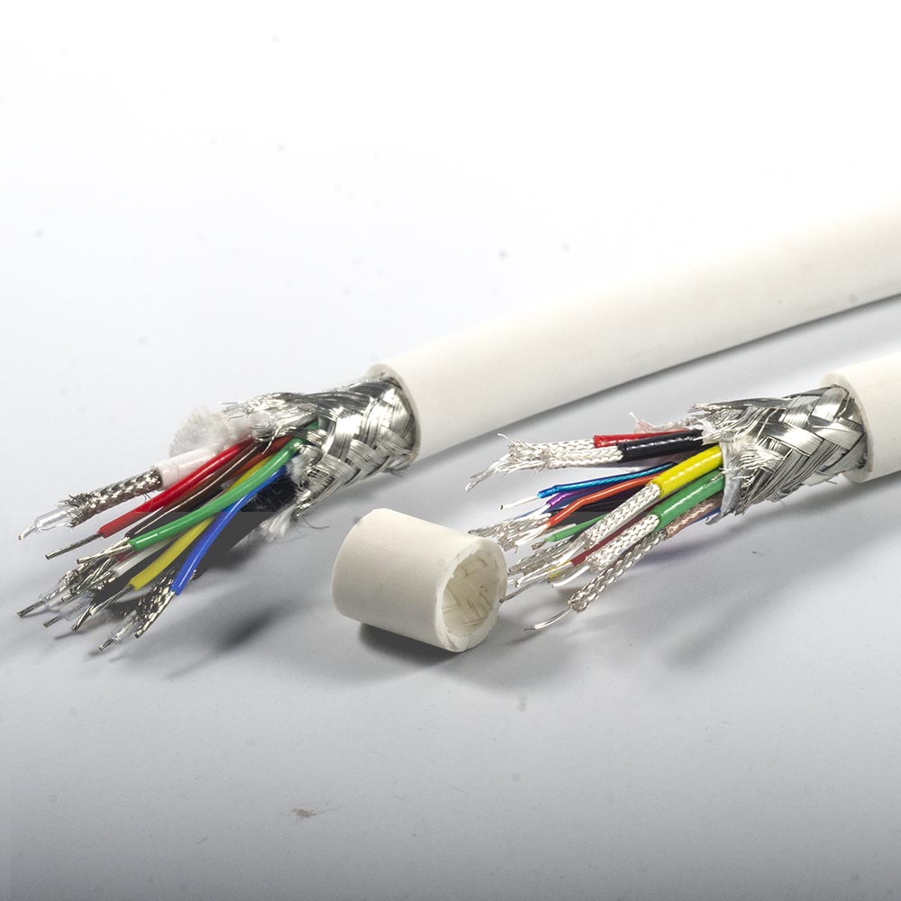
Shielding Effectiveness (EMI Control in MRI Environment)
MRI systems are extremely sensitive to electromagnetic interference (EMI).
Cables must provide strong shielding while maintaining flexibility.
Typical Shielding Structures
- Braided shielding (≥85% coverage)
- Foil + braid (double shielding)
- Multi-layer RF shielding design
Target Performance
Engineering-grade MRI cables typically aim for:
Shielding effectiveness: 60–90 dB (depending on frequency)
Why Shielding Matters
Proper shielding helps:
- Prevent external EMI interference
- Reduce RF radiation from the cable
- Improve signal stability
- Reduce imaging artifacts
RF-Induced Heating & MRI Safety
In strong RF environments, cables may experience induced currents, which can lead to:
- Localized heating
- Patient safety risks
- Unstable RF performance
Main Causes
- Common-mode currents
- RF antenna effect
- Poor shielding continuity
Engineering Design Strategies
To reduce RF-induced heating:
- Symmetrical cable structures are used
- Shield continuity is carefully controlled
- Cable geometry is optimized for RF stability
MRI Compatible Materials (Beyond “Non-Magnetic”)
MRI cables require more than just non-magnetic materials.
Material selection must ensure both safety and signal stability.
Magnetic Requirements
Materials must have:
- Very low magnetic susceptibility
- No ferromagnetic behavior
- No influence on MRI image quality
Reference Standards
MRI-compatible materials are typically evaluated according to:
- ASTM F2503 – MRI safety classification
- ASTM F2052 – Magnetic displacement force testing
Typical Material Selection
| Component | Typical Material |
|---|---|
| Conductor | Copper / Silver-plated copper |
| Dielectric | FEP / PTFE |
| Outer Jacket | PVC / TPU |
Engineering Goal
Materials must be:
- Non-ferromagnetic
- RF stable
- Resistant to imaging artifacts
- Suitable for repeated bending
Signal Integrity & Imaging Quality (SNR)
Poor cable design may result in:
Reduced signal-to-noise ratio (SNR)
RF noise interference
Signal attenuation
Imaging artifacts
Engineering Target
A high-quality MRI cable must:
- Maintain stable performance at Larmor frequency
- Minimize interference with proton (¹H) signals
- Provide consistent RF transmission performance
Testing & Validation Methods
Professional MRI cables are not evaluated only by appearance or material.They must pass multiple engineering tests.
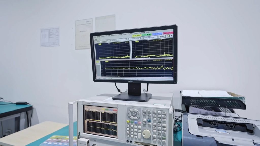
1. RF Electrical Testing
Using a Vector Network Analyzer (VNA):
- S11 (reflection / return loss)
- S21 (insertion loss)
- Frequency stability testing
2. Shielding Effectiveness Testing
- EMI testing
- Frequency sweep validation
- RF shielding performance measurement
3. MRI Environment Testing
Testing in simulated MRI conditions (phantom testing):
- Temperature rise evaluation
- Signal stability testing
- Image artifact verification
4. Mechanical Reliability Testing
- Flex life testing
- Bending radius validation
- Long-term durability testing
Custom MRI Cable Engineering Solutions
Micro coax cable assemblies
Multi-core MRI cable design
High shielding RF cable solutions
Low-loss cable structures
Suitable For
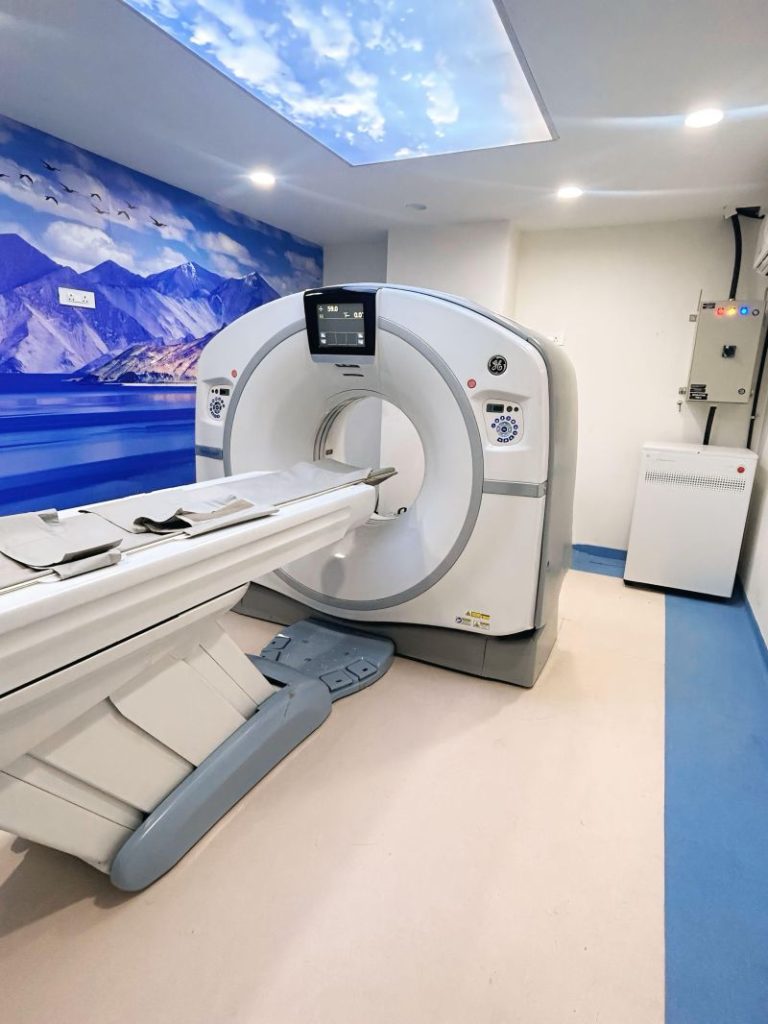
- MRI coil cable replacement
- MRI system maintenance
- Medical imaging equipment
- Diagnostic device cable assemblies
Request Engineering Support
ooking for a custom MRI cable?
As a MRI Cable Manufacturer We can provide engineer design support:
- 1.5T / 3T system requirements
- 50Ω RF cable design
- Custom cable structures
- Engineering design support
👉 Send us your drawing or sample and our engineering team will provide a solution. or refer to our experienced MRI Coil Cable