Introduction
When repairing or replacing a shaver handpiece cable, many technicians notice an apparent mismatch:
the cable contains 16 cores, while the connector features 19 pins.
This often leads to confusion:
- Are some wires missing?
- Is the cable incorrectly designed?
- Should i custom a 19 conductor cables?
- Can it still function properly?
In this guide, we explain how a 16-core medical cable works with a 19-pin connector, and what this means for 72200616 cable repair and replacement.
Understand how a 16-core cable works with a 19-pin connector in shaver handpiece systems. Structure, shielding, and repair guide for 72200616 cable replacement.
What configure is this 16-Core Shaver Handpiece Cable?
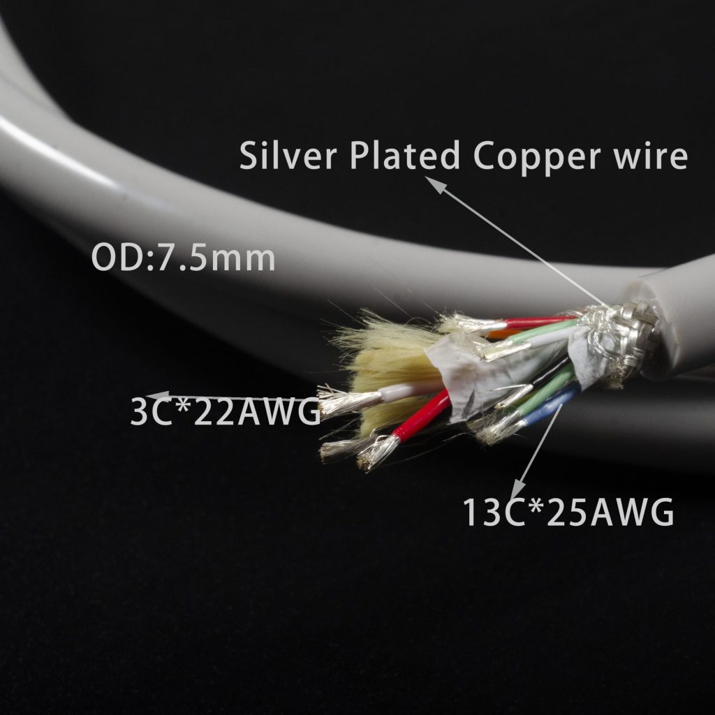
This 16-core cable refers to a cable that contains 16 individual conductors inside its structure. These conductors are responsible for transmitting power, control signals, or feedback signals between the surgical handpiece and the console.There is 3 conductor 22AWG and 13 conductor of 26AWG (some customer order a custom solution with 3 conductor 21AWG and 13 conductor of 25AWG. According to our different repairer clients feedback ,boto configure works well
In medical applications such as arthroscopic systems, the cable is typically designed with:
- Multi-core copper conductors: 3 conductor 22AWG and 13 conductor of 26AWG
- Optional coaxial or signal pairs:as the frequency is not high,no coaxial or twisted pair is needed
- Well shielding :Silver plated copper alloy braiding + PTFE tape
- Medical-grade silicone outer jacket:No mess,No sticky(after processing),suitable for Autoclave sterrilization
- Strength member:a handpiece is moved every moments when it is working,that is the main reason why it is easy to break and the bring the birth of “Repair Market“—-Alloy Conductor+Kevlar Strength member(Filler) is used for this purpose
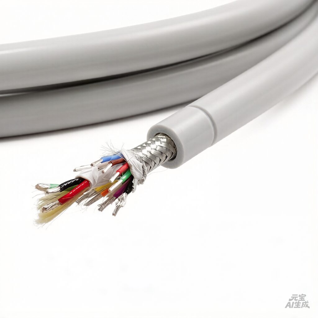
This structure ensures high flexibility, low signal interference, and long service life, which are critical in surgical environments where cables undergo frequent movement and bending.
Why Does the Connector Have 19 Pins?
A 19-pin connector does not necessarily require 19 independent conductors. Instead, the extra pins are often used for:
- Signal redundancy
- Ground distribution
- Contact reliability enhancement
- Mechanical stability
In many surgical handpiece cable designs, some pins are internally connected (bridged), meaning multiple pins share the same electrical path.
This allows the system to maintain stable electrical performance without increasing the number of conductors inside the cable.
How 16 Cores Work with 19 Pins
In a typical 72200616 cable structure, the relationship between cores and pins is based on pin sharing (bridging design).
Actual Pin Mapping in 72200616 Cable (Example)
Step-by-Step 72200616 Shaver Cable Repair Blueprint
To successfully map a 16-core bulk cable onto a 19-pin arthroscopic connector without triggering short circuits, technicians must abandon the “one-core-to-one-pin” assumption and implement this verified bridging schema.
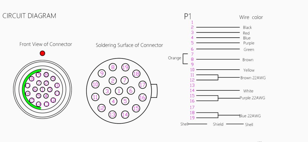
1. Definitive Pin Mapping & Gauge Allocation Table
The 19-pin connector architecture relies on intentional internal bridging to enhance contact reliability and distribute current loads. Instead of running separate wires, certain pins share a single high-gauge conductor path.
| Conductor Group | Wire Gauge (AWG) | Target Connector Pins | Internal Wiring Connection Status |
|---|---|---|---|
| Power Distribution | 22 AWG | P7 & P9 | Bridged to a single 22AWG core |
| System Grounding | 22 AWG | P18 & P19 | Bridged to a single 22AWG core |
| Control Signal A | 26 AWG | P11 & P12 | Bridged to a single 26AWG core |
| Feedback Loop | 26 AWG | P15 & P16 | Bridged to a single 26AWG core |
| Isolated Signals | 26 AWG | Remaining 9 active pins | Independent 1-to-1 routing |
| Dead Pins (Unused) | – | P1, P13, P17 | No Connection (Leave Open) |
2. Post-Soldering Quality Control Protocols (Electrical Validation)
Once your 16 conductors are terminated according to the schema above, perform this 3-step electrical validation before overmolding the rubber boot:
- Micro-Ohmic Continuity Test: Deploy a digital multimeter in resistance mode to measure the connection across the bridged pins (e.g., test from the tip of Pin 7 to Pin 9). The reading must be below 0.2Ω. Any higher indicates a cold solder joint that will drop voltage under load.
- Shielding Insulation Inspection: Medical shaver cables operate near high-frequency noise sources. Check the isolation between the silver-plated copper alloy outer braid and the internal conductors. The insulation resistance must exceed 100 MΩ under a 250V DC test.
- Hermetic Sterilization Seal: Ensure the interface between the medical-grade silicone jacket and the 19-pin connector shell is completely fluid-tight. If moisture leaks into the boot during a 134°C autoclave cycle, it will cause rapid pin corrosion and intermittent feedback errors.
Advanced Troubleshooting for Shaver Cable Replacements
Why choose a 16-core layout instead of a native 19-conductor cable?
A native 19-conductor cable would dramatically increase the overall outer diameter (OD) and mechanical stiffness, causing severe hand fatigue for surgeons. By using advanced rope-lay stranding across 16 cores and utilizing internal pin-bridging for redundancy, we deliver the exact same electrical performance while maintaining an ultra-flexible, lightweight 7.5mm profile.
What happens if the unused pins (P1, P13, P17) are accidentally crossed?
Pins 1, 13, and 17 are reserved by the console’s digital logic framework. Forcing a stray copper strand into these slots can feed back phantom voltages to the control board, resulting in “Handpiece Not Detected” errors or immediate console system lockouts.
Can custom outer jacket colors or custom laser markings be specified for repair batching?
Yes. To assist specialized medical depot repair companies in tracking inventory or differentiating hospital departments, we provide custom jacket extrusions (Blue, Grey, Black) and sequential surface printing upon request.
What This Means:
This confirms that the cable uses a 16-core structure mapped onto a 19-pin connector, where:
- Some pins are intentionally left unused
- Some pins are duplicated to improve electrical or mechanical performance
Why This Design is Used:
- Improves contact reliability (dual-pin contact)
- Enhances signal stability
- Reduces wear on individual pins
- Maintains compatibility with system interface design
Important for Repair:
Do NOT match wires based only on pin count
✔ Always follow correct pin mapping and circuit logic
Incorrect assumptions may lead to:
- Signal failure
- Device malfunction
- Reduced cable lifespan
Can You Customize or Supply Cable Materials?
Yes. Depending on your repair needs, different options are available:
Available Solutions:
- Complete cable assembly
- 16-core bulk cable material
- Connectors (19-pin)
- Metal caps / strain relief components
- Custom cable processing and assembly
We also support:
- Customer-supplied components
- Cable cutting, stripping, soldering
- Connector termination and overmolding
- Parts souring service
This is especially useful for medical cable repair companies looking for flexible and cost-effective solutions.