Semi-finished ultrasound cable solutions for probe manufacturers and repair service providers
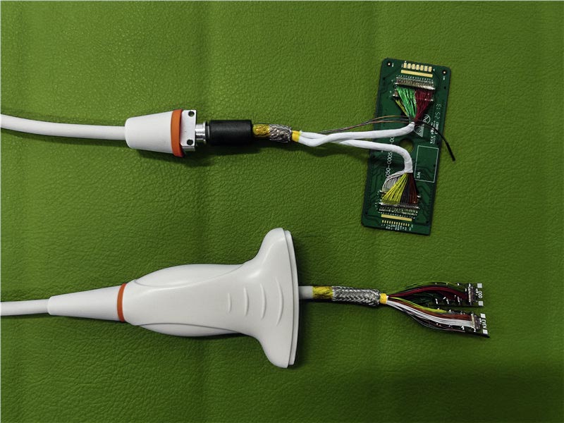
Our pre-soldered PCB ultrasound probe cable assemblies combines the structural advantages of premium micro-coaxial raw cable production with full transducer-end integration. By pre-soldering high-density PCBs on both termination ends and ensuring sub-millimeter cable routing and shielding, we eliminate the most complex micro-soldering steps in the assembly pipeline.
This semi-finished approach leaves flexible spacing for overseas transducer manufacturers and medical imaging repair service providers to finalize the probe housing with their own acoustic matrix or piezoelectric crystal components.
Importance of Cable Quality in Ultrasound Imaging
Why Cable-to-PCB Soldering Requires Special Assembly Design
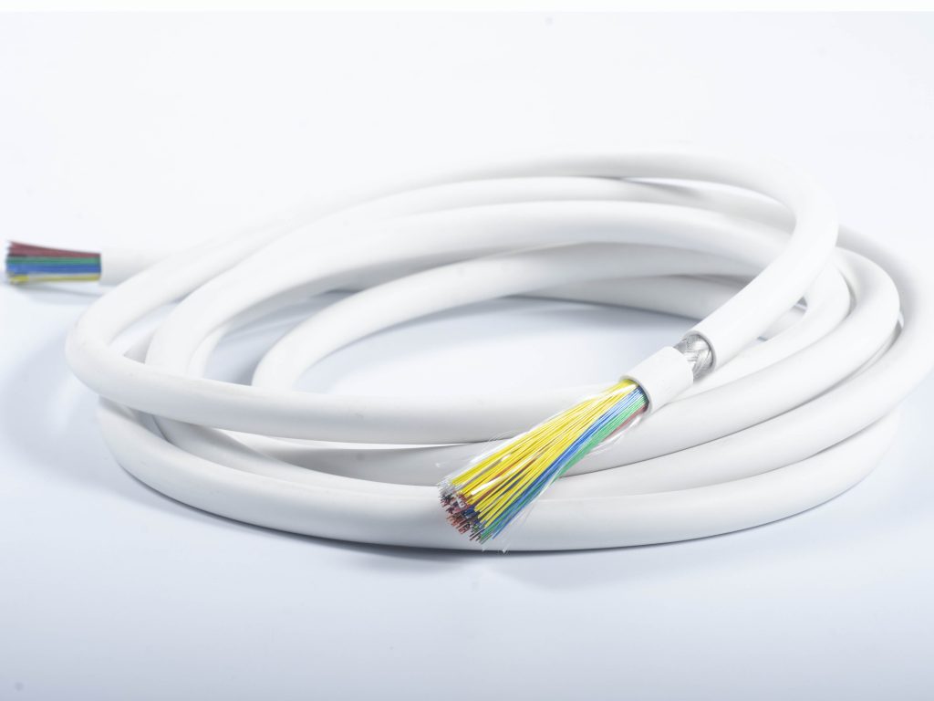
In high-channel-count imaging (ranging from 68 to 256 cores of ultra-fine 36AWG to 44AWG micro-coaxial wires), direct hand-soldering carries immense structural risks. Any slight overpressure or thermal fluctuation during the reflow or hand-soldering process can degrade the thin insulation jacket, permanently changing the cable’s capacitance (50 pF/m) or characteristic impedance (85Ohm).
Our facility utilizes CCD-guided micro-soldering technology to ensure zero thermal damage to the internal fluoropolymer dielectric layer, maintaining absolute signal integrity and a flawless signal-to-noise ratio (SNR) for weak echo wave returns.
Key Components of a Piezoelectric Ultrasound Probe
Each probe contains elements like:
• Piezoelectric wafers (usually quartz or ceramic)
• Damping blocks
• EMI shielding and protective housing
• Signal cable and connector interfaces
The piezoelectric wafer plays a core role in converting electrical signals into ultrasound and vice versa, enabling both transmission and reception. Damping materials help reduce noise and echo artifacts, improving image resolution.
what we offer
We manufacture custom ultrasound probe cable assemblies — the critical cable portion connecting the probe head to the system. Our assemblies are equipped with pre-soldered PCBs at both ends, excluding the matrix and piezo crystal, which allows flexible final assembly at the customer’s side.
 Custom ultrasound cable manufacturing for C5 2E
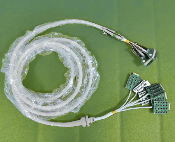 Ultrasound probe cable assemblies with PCB for GE C1 6 D transducer
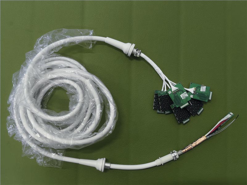 ic5 9 d probe Ultrasound probe cable with PCB
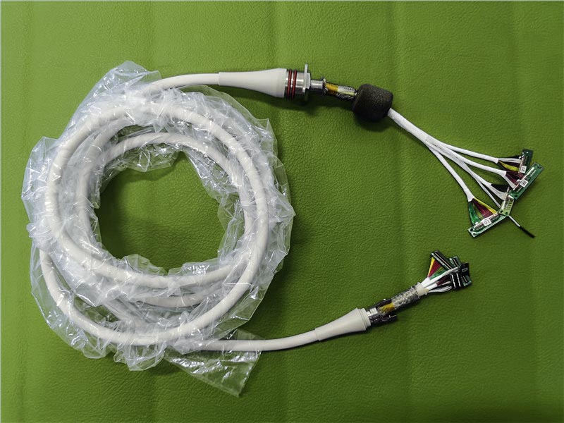 Ultrasonic transducer cable assembly 12 2
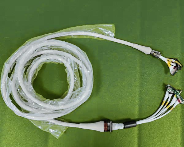 Medical ultrasound cable for repair philips c5 1 transducer
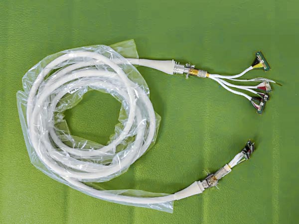 Compatible c5 1 probe Ultrasound probe cable with PCB for philips cx50 probes
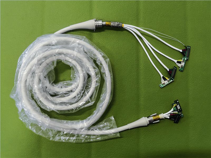 l12 5 transducer Cable assembly
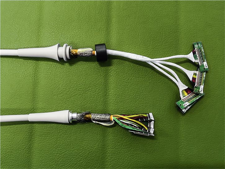 plt 805at Ultrasound cable assembly with PCB
Who Needs This Product
• Ultrasound probe manufacturers
• Medical device /Ultrasond probe/Transducer repair companies
• OEMs and R&D labs developing new probes
• Distributors of semi-finished medical components
Engineering Checklist for Ultrasound Probe Cable Compatibility
Before ordering or engineering a custom compatible probe cable assembly, technical procurement teams must verify the following parameter matchings:
- Conductor & Gauge Mapping: Confirm if the system requires ultra-fine 42AWG/44AWG micro-coax for high-frequency probes (>10MHz) or 36AWG/38AWG for standard abdominal arrays.
- Pinout & PCB Footprint Alignment: Ensure the pitch of the pre-soldered PCB matches the termination board of your transducer matrix (e.g., connectorized vs. direct solder pad layout).
- Strain Relief & Bend Radius: The transition zone between the bulk line and the rigid PCB must incorporate tailored medical-grade strain relief boots to distribute stress during dynamic clinical scanning.
- Cross-Talk Shielding Topology: High-density channels must feature individual coaxial shields integrated with an overall non-magnetic braided outer shield to block RF interference from clinical equipment.
Brand Compatibility and Repair Support
Our advanced integration workshop supports manufacturing and refurbishment cable bundles fully compatible with major diagnostic imaging platforms, including:
- GE series: C1-6-D Convex, iC5-9-D, and logic-series array cable replacements.
- Philips series: L12-5 Linear, C5-1 Cable Assemblies for iE33/iU22, and CX50 portable probes.
- Universal Cart Support: Tailored termination PCBs compatible with Siemens, Mindray, Toshiba PLT-805AT, Aloka, and Hitachi transducer architectures.
Useful tips
Evaluate Manufacturing Capabilities of an Ultrasound Probe Cable Assembly Provider
- CCD-guided micro-soldering
- Clean and reliable cable routing
- OEM/ODM friendly
- Global shipping and responsive service
Best Practices & Maintenance
- Ensure compatibility with probe system
- Avoid excessive bending or twisting
- Clean only with non-corrosive solutions
- Replace if signal transmission degrades
FAQ: Tech Insights for Transducer Engineering
What parameters should be verified for a cable assembly with a soldered PCB?
You must verify the matching of characteristic impedance (typically $75\Omega$, $85\Omega$, or $90\Omega$) and nominal capacitance. Furthermore, the thermal tolerance of the cable jacket must withstand the encapsulation or potting resins used during the final acoustic head assembly.
Can you support connectorless solder pad ultrasound cable terminations?
Yes, we specialize in both connectorized interfaces and open-ended connectorless layouts. We provide clean, pre-tinned, and laser-stripped micro-coaxial leads landed precisely on custom array PCBs, allowing plug-and-play matrix connection.
Why does low capacitance (50 pF/m) matter in multi-channel probe assemblies?
Low capacitance directly reduces the phase delay and high-frequency attenuation of the weak echo signal traveling back from the piezoelectric crystal. It preserves the bandwidth of high-element probes, resulting in sharper B-mode contrast and precise Doppler tracking.